Working principle of vacuum atmosphere muffle furnace
 09-12-2025 Author: KJ technology
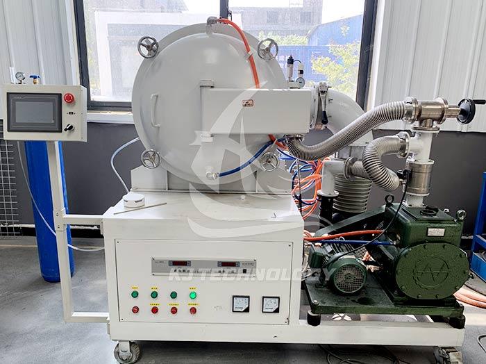
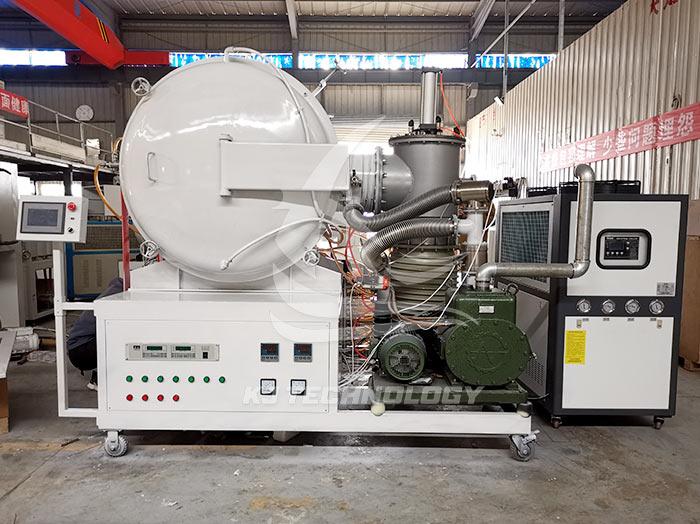
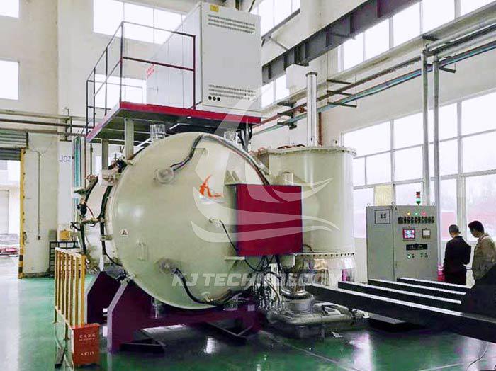
The vacuum atmosphere muffle furnace is a high-temperature heating equipment that integrates vacuum environment control and atmosphere regulation functions. Its working principle is achieved through the synergistic effect of the vacuum system, heating system, atmosphere control system, and temperature control system. The following is a detailed analysis of its core working principle:
1. Vacuum system: creating an anaerobic environment
Vacuum pump operation
Extraction process: The air inside the furnace is extracted through a rotary vane pump or molecular pump to create a vacuum environment. Rotary pumps are suitable for rough vacuum (10 ⁻³ Pa), while molecular pumps can achieve high vacuum (10 ⁻⁴ Pa).
Vacuum degree adjustment: According to experimental requirements, the vacuum degree is controlled through valves. For example, low vacuum (10 ⁻¹ Pa) is required during metal annealing, while high vacuum (below 10 ⁻⁴ Pa) may be required for semiconductor doping.
vacuum sealing
Sealing structure: Fluororubber O-ring or metal dynamic seal (such as magnetic fluid seal) is used to ensure that there is no leakage in the furnace door, flange interface and other parts.
Leak detection method: Use a helium mass spectrometer leak detector to detect small leaks and ensure the stability of the vacuum environment.
2. Heating system: achieving high temperature control
heating element
Resistance wire: suitable for low temperature (≤ 1000 ℃) scenarios, low cost but prone to oxidation.
Silicon carbon rod: resistant to high temperatures (1300 ℃ -1600 ℃), suitable for oxidizing atmospheres, but with poor thermal shock stability.
Silicon molybdenum rod: can be used for a long time at 1600 ℃ -1800 ℃, with good thermal shock resistance, but the price is relatively high.
Heating method
Radiation heating: The heating element transfers energy to the sample through thermal radiation, suitable for uniform heating in tube furnaces.
Convection heating: Under atmospheric flow conditions (such as introducing gas), temperature uniformity is accelerated through thermal convection.
Temperature uniformity control
Furnace design: Adopting a double-layer insulation structure (such as ceramic fiber cotton+mullite bricks) to reduce heat loss.
Thermocouple layout: Multiple thermocouples (such as N-type and S-type) are arranged at different positions in the furnace to monitor temperature in real time and provide feedback to the PID controller.
3. Atmosphere control system: regulating gas environment
gas introduction
Inert gases: such as nitrogen and argon, used to protect samples from oxidation (such as metal sintering).
Reducing gases: such as hydrogen and carbon monoxide, used for reducing metal oxides (such as iron ore reduction).
Reactive gases, such as methane and ammonia, are used for chemical vapor deposition (CVD) or carburizing treatment.
Gas flow control
Mass flow meter (MFC): Accurately control gas flow rate (such as 0-1000sccm) to ensure atmosphere stability.
Gas mixture ratio: Different gases are mixed in proportion through multiple MFCs (such as Ar: H ₂=95:5).
Atmosphere cycle
Gas circulation pump: Forces gas flow in a closed furnace to improve temperature and atmosphere uniformity.
Exhaust gas treatment: Burning or adsorbing toxic or flammable gases (such as H ₂) to ensure safe emissions.
4. Temperature control system: precise control of temperature curve
PID control algorithm
Proportional integral derivative adjustment: By comparing the set temperature with the actual temperature in real time, the heating power is dynamically adjusted to eliminate overshoot and oscillation.
Self tuning function: Automatically optimize PID parameters based on furnace thermal inertia to shorten heating time.
Temperature program setting
Multi stage programming: supports independent settings for heating, insulation, cooling and other stages (such as "30 minutes heating to 800 ℃, insulation for 2 hours, natural cooling").
Slope control: Limit the heating rate (e.g. ≤ 5 ℃/min) to prevent sample thermal stress cracking.
safety protection
Overtemperature alarm: When the temperature exceeds the set value ± 5 ℃, the heating power supply will be automatically cut off and an alarm will be triggered.
Broken thermocouple protection: When the thermocouple breaks, the system automatically enters safe mode to avoid accidental heating.
5. Collaborative workflow example (taking ceramic sintering as an example)
Vacuum pumping stage: Start the rotary vane pump to pump the furnace vacuum to 10 ⁻ Pa and remove air.
Introduce protective gas: Slowly introduce high-purity nitrogen gas to atmospheric pressure, repeat the vacuum and ventilation operation 3 times, and completely remove residual oxygen.
Heating sintering: Set the heating program (such as raising to 1600 ℃ for 2 hours), and the PID controller dynamically adjusts the power of the silicon molybdenum rod based on feedback from the thermocouple.
Insulation treatment: Keep at 1600 ℃ for 4 hours to ensure sufficient growth of ceramic grains.
Cooling stage: Stop heating, introduce nitrogen gas to accelerate cooling to below 200 ℃, open the furnace door and take out the sample.
6. Influence of key technical parameters
Parameter influence
Insufficient vacuum degree can lead to sample oxidation, while high vacuum can reduce the absorption of thermal radiation by gas molecules.
The material of the heating element is silicon molybdenum rod, which is more heat-resistant than silicon carbon rod, but the cost of the resistance wire is the lowest.
Low gas flow rate can lead to uneven atmosphere, while high flow rate may cause sample blowing or furnace pressure fluctuations.
Temperature control accuracy of ± 1 ℃ is suitable for semiconductor processes, and ± 5 ℃ can meet general metal heat treatment requirements.
7. Common Problems and Solutions
Insufficient vacuum degree
Reason: Aging of sealing ring and contamination of vacuum pump oil.
Solution: Replace the sealing ring, clean or replace the vacuum pump oil.
temperature overshoot
Reason: PID parameters not optimized, thermocouple position offset.
Solution: Re tune the PID and correct the installation position of the thermocouple.
Uneven atmosphere
Reason: Low gas flow rate, furnace structural defects.
Solution: Increase gas flow rate and optimize the design of gas guide plates in the furnace.


